
More completely, the RMS level is, “the square root of the arithmetic mean of the signal squared.” The magnitude is calculated by squaring each sample value (so they are all positive), then the signal average is calculated, eventually followed by the square root operation. It is based on the magnitude of a signal as a measure of signal strength, regardless of whether the amplitude is positive or negative. This is where the RMS level can be useful.

#Bipolar square wave with eak amplitude full#
Since finding a full derivation of the formulas for root-mean-square (V rms) voltage is difficult, it is done here for you. That 1 V rms square wave has a peak voltage of 1 V, and a peak-to-peak voltage of 2 V. Instead, the DS5 will produce an isolated constant current stimulus proportional to a voltage applied at its input, with the shape of the input waveform describing the shape of the stimulus. A 1 V rms square wave applied across a 1 resistor also produces 1 W of heat. This approach is not informative about the average signal level. Unlike other clinical stimulators, the DS5 is not a traditional 'square wave pulse stimulator'. If we took the arithmetic mean of a sine wave, the negative values would offset the positive values and the result would be zero. However, it is different than simply measuring the arithmetic mean of a signal.Īn audio signal can have both positive and negative amplitude values.

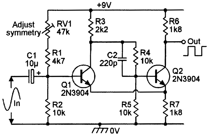
Conceptually, it describes the average signal amplitude. If you choose rail to rail op-amps and have a stable + and - 5 volt rails then you can probably rely on the square wave output's amplitude from the first stage.An analysis used for the overall amplitude of a signal is called the root-mean-square (RMS) amplitude or level. The receiver has an analog gain up to 92 dB. With this Phased Array solution, you can measure even deeper at a better resolution. That gain can be tweaked to set the output precisely at +/- 5 volts. The square-wave pulsers are running at 200 Volts peak-to-peak and feature a special circuitry to maximize the transfer of piezoelectric energy. This would then mean that the 2nd stage filter will need a gain of 2 to obtain +/- 5 volts peak to peak. I might also consider that to give a reasonably constant output amplitude, the output from the oscillator is limited by precision voltage shunts (possibly LT1389 or SPX4040) to restrict the output to +/- 2.5 volts. 1, three pairs of electrodes are employed. Those two components are there to remove any DC offset from the oscillator because that sort of oscillator is going to produce an offset that is generally undesireable due to asymmetries in the output limiting. 1, the voltage applied to each electrode 100a-f may be a bipolar square wave. Next I would ensure that the output from the first stage (the relaxation oscillator) fed the 2nd stage (a 2nd order low pass filter) via a decoupling capacitor and resistor to ground. R4 would also need to connect to the negative rail. The split bipolar supply also naturally gives you a centre point of 0 volts (desireable). This gives enough supply overhead to produce a sensible output level of a 5 volt peak sine wave. One method is the use of the inverter bridge (also known as an H-bridge), which is illustrated in Figure 4. MCQs: Consider a square wave having a peak to peak amplitude of 275mv and it is amplified to a peak to peak amplitude of 4v, with rise time of 5.2µs. A switching circuit is used in the conversion of DC voltage to an alternating (or bipolar) square wave voltage. I'd start by powering both op-amps with bipolar supplies, something like +/- 9 volts. Figure 3 Harmonic Content of a Square Wave. I was wondering what changes to the circuit would be needed to change


 0 kommentar(er)
